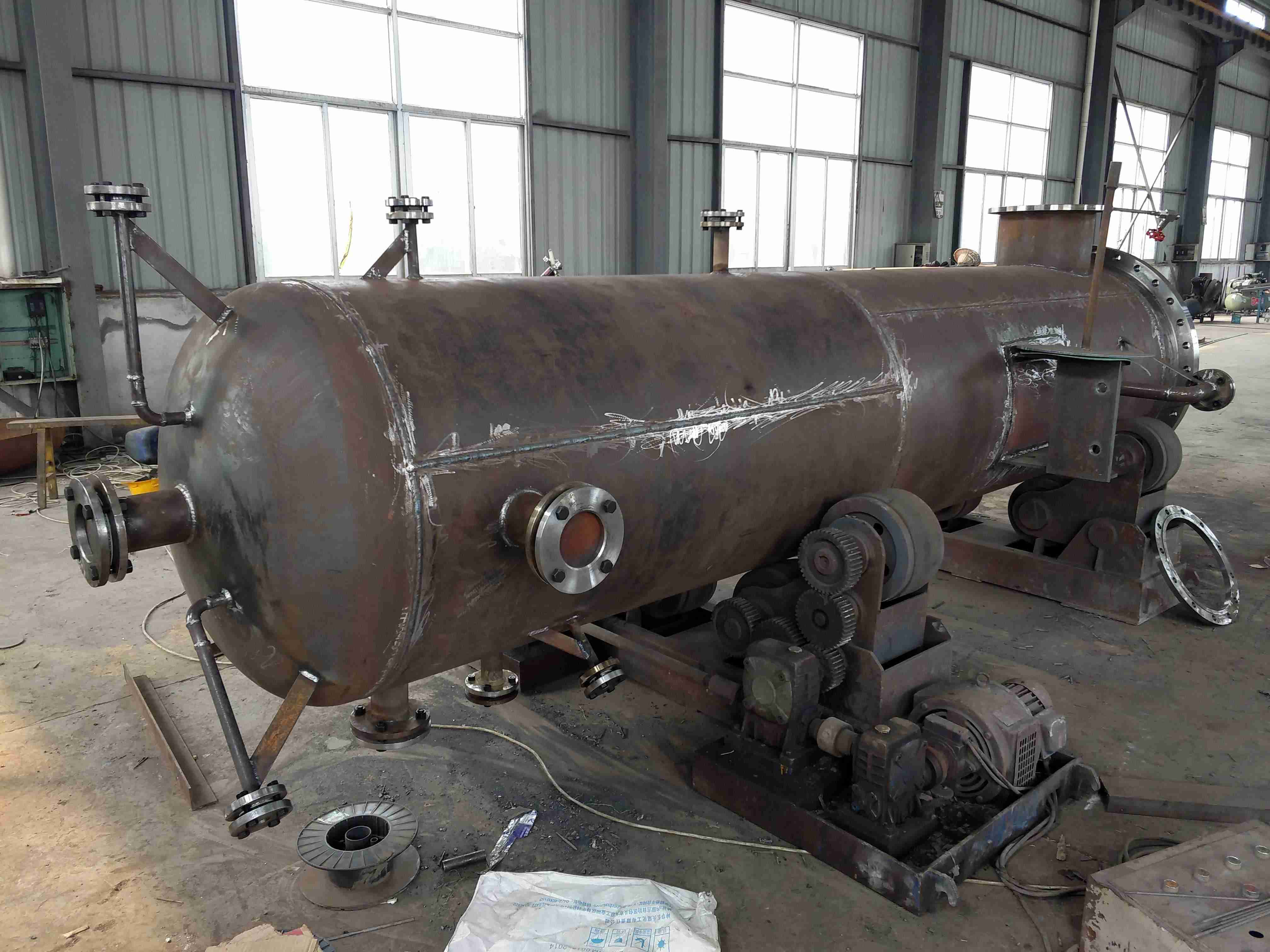
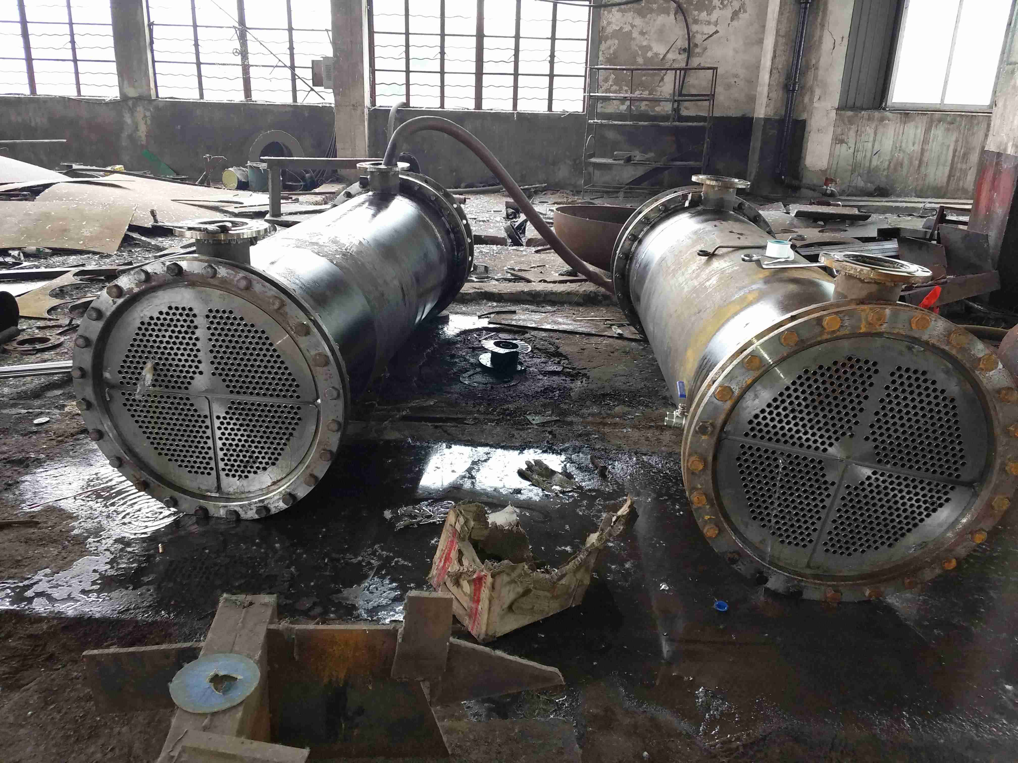
铂莱娱乐场Introduction to steam seal heater:
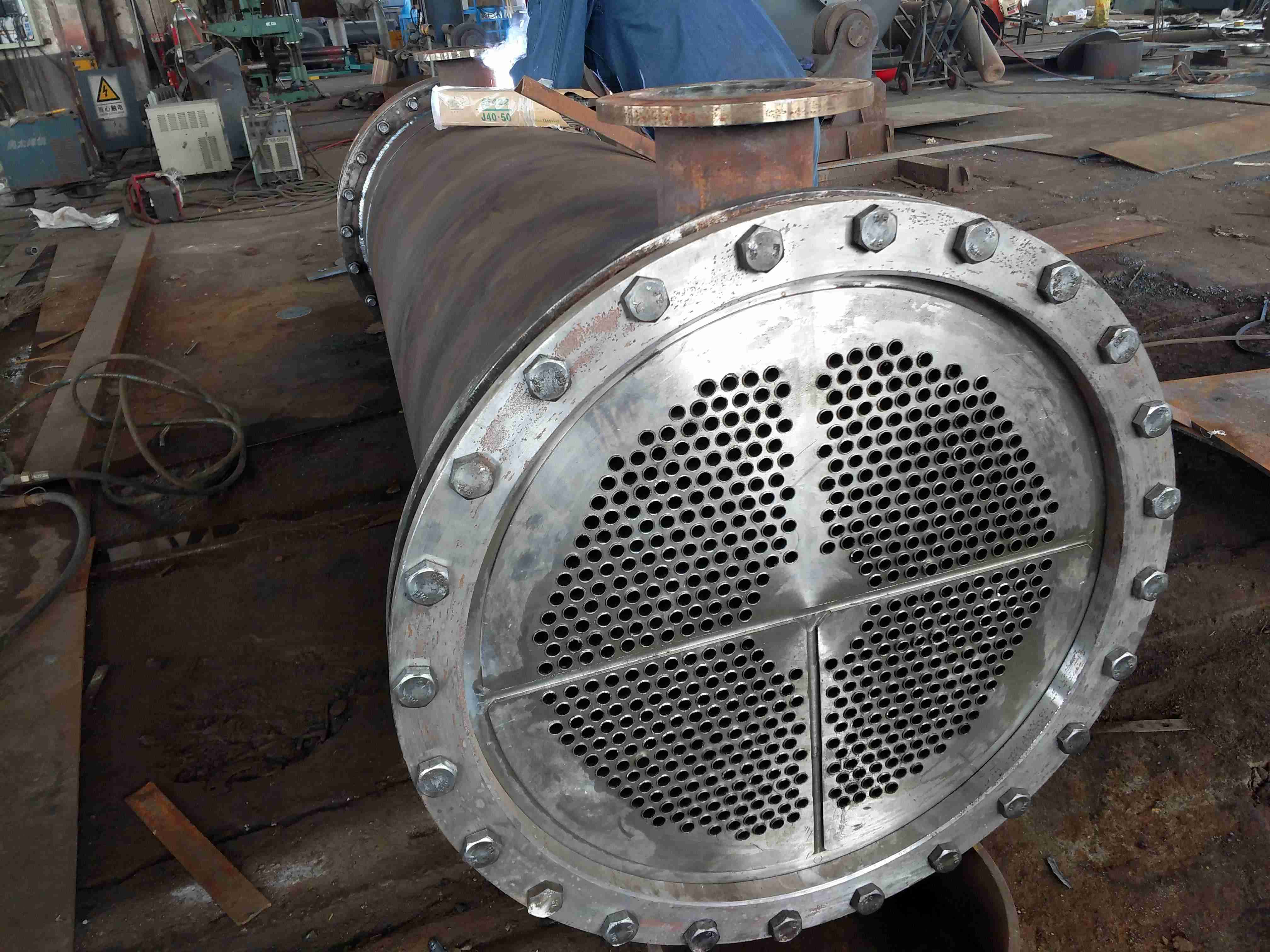
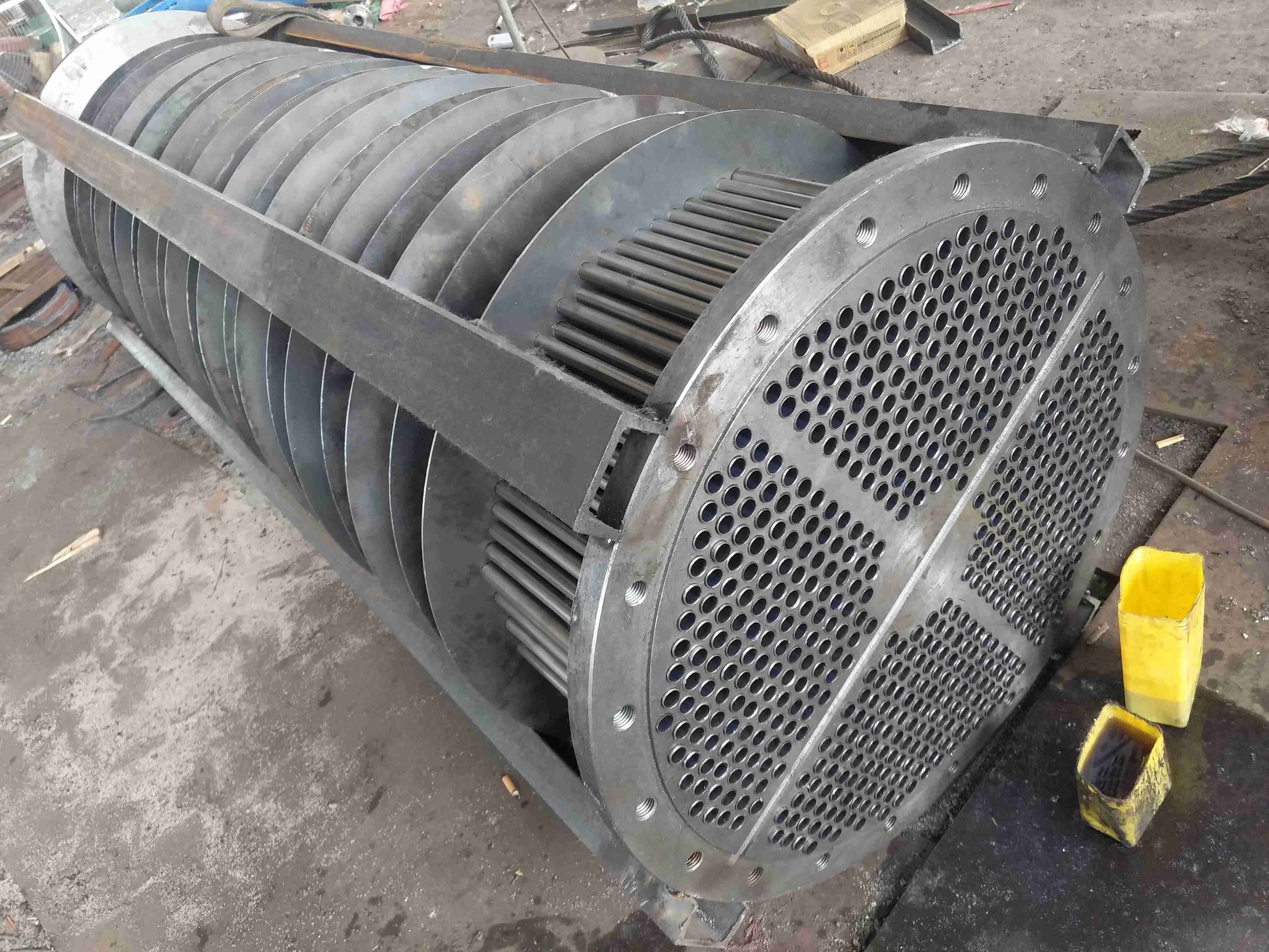
The water side of the heat exchanger of the steam seal heater, also known as the shaft seal heater, adopts a four process structure. The cooling water enters the water chamber from the inlet of the steam seal cooler and then flows into the tube bundle of the shell. When the cooling water flows inside the heat exchange tube, it exchanges heat with the steam entering the shell (steam side). The cooling water absorbs a large amount of steam condensation heat, and the water temperature rises before entering the outlet water chamber, And overflow the steam seal cooler through the cooling water outlet. The steam from the turbine rear shaft seal enters the inner side of the casing through the steam pipeline and enters the steam inlet of the steam seal heater. Steam flows through the guide plate inside the shell and continuously flows between the heat exchange tubes of the tube bundle, conducting heat exchange. Most of the steam releases a large amount of heat when passing through the outer wall of the heat exchange tubes and condenses into water. The condensed water is discharged from the drain outlet and enters the drain pipe. Due to the presence of some non condensable air in the steam, in order to continuously pass through the steam pipeline and enter the steam seal cooler, the gas needs to be extracted and discharged into the atmosphere through a steam injector, along with residual steam.
Selection of pipe materials for replacing steam seal heaters:
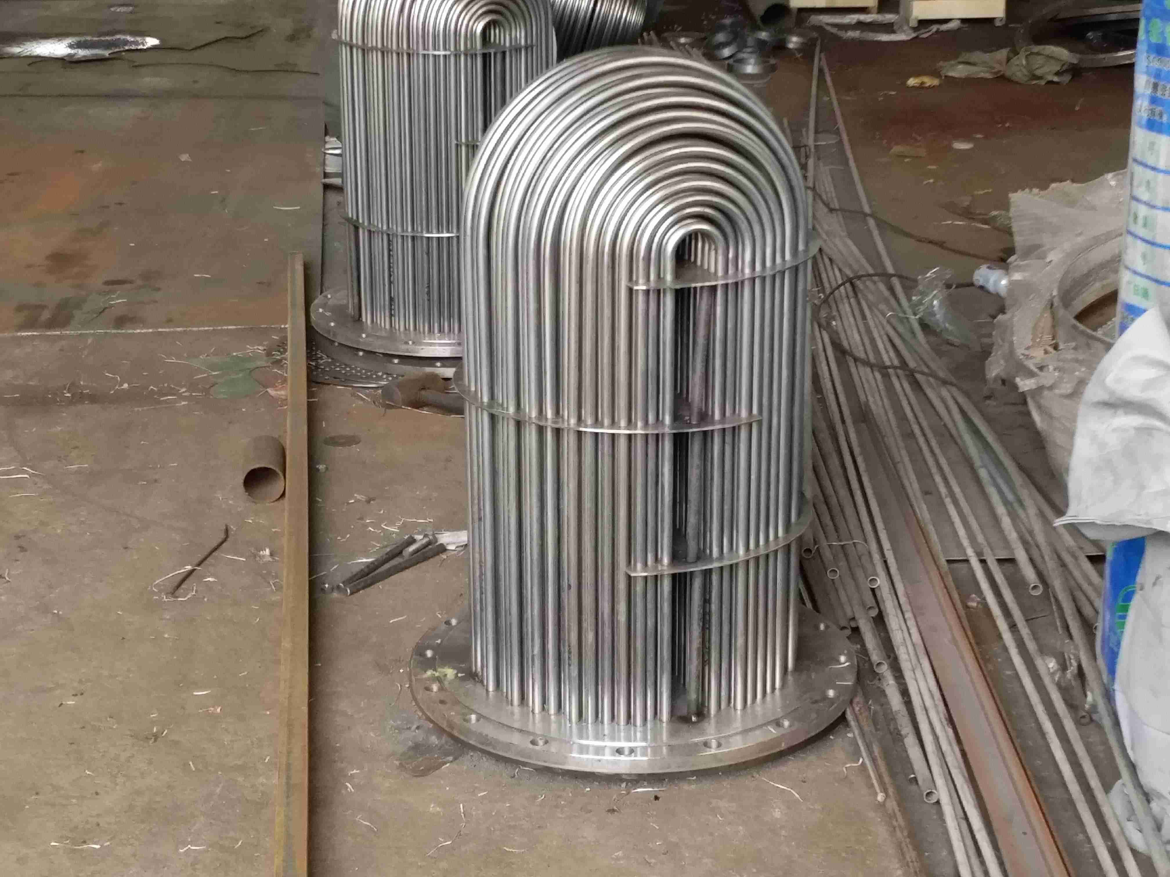
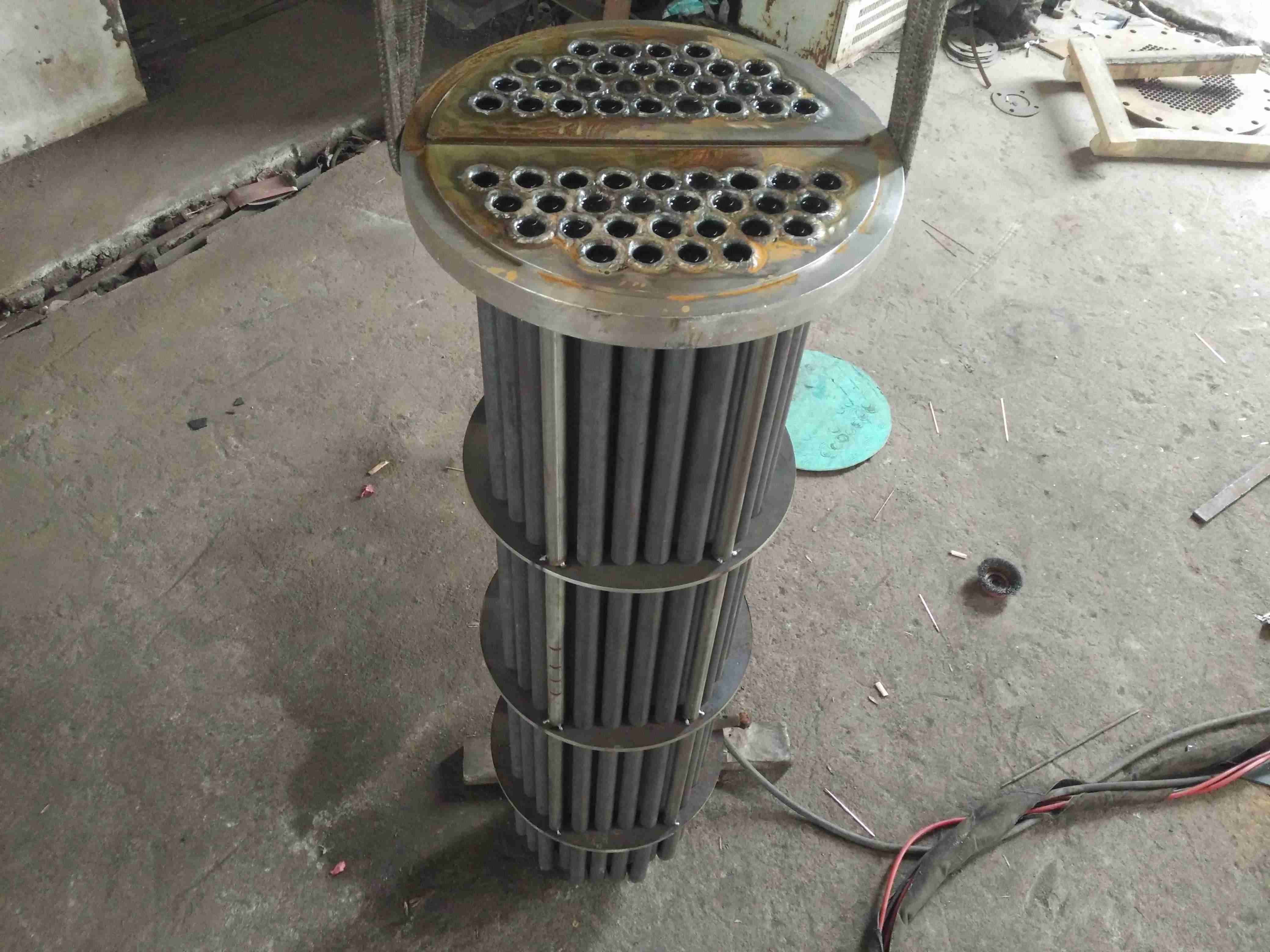
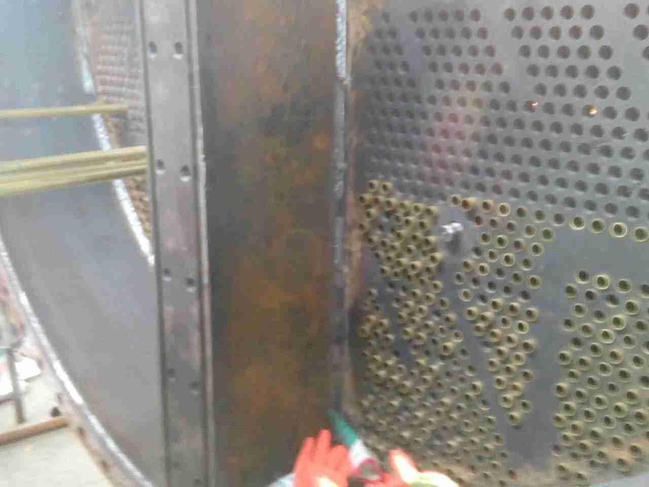
The steam seal cooler generally adopts a horizontal U-shaped surface heat exchanger for pipe replacement, and the pipe material is stainless steel pipe. In addition to expansion joint, the pipe also needs to be sealed and welded with the pipe plate; HSn-70-1 tin brass is also used, which is fixed on the tube plate by expanding the tube bundle to the U-shaped tube end freely. But for critical and critical unit steam seal heaters, stainless steel pipes must be selected for pipe replacement.
Sealing heater tube replacement issue - quality:
铂莱娱乐场At first, the operation was positive, but after running for about half an hour, there was a problem, which was manifested as two steam bursts from the turbine and no gas being discharged from the vent pipe of the steam seal heater! After the vent pipe of the steam seal heater is opened, it is full of water, and this situation is too long. The steam seal cooler is full of water! If such a phenomenon occurs, it can be basically confirmed that the condensation - if too much steam is condensed into liquid and not released immediately, then there may be leakage in the inner floating head due to the presence of - - in the tube side, or if your tube side and shell side are not integrated, it is possible that the inner floating head cushion inside has not been tampered with, resulting in leakage of the inner floating head and other conditions. If there is -- inside the tube bundle, then the problem is significant and the tube needs to be replaced.
Sealing heater tube replacement structure - potential:
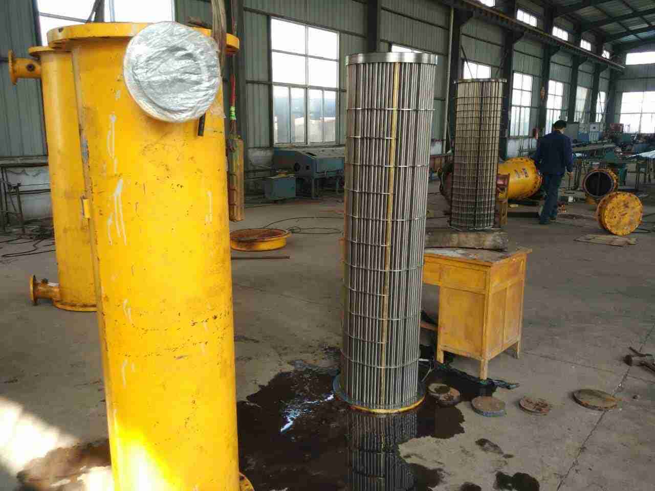
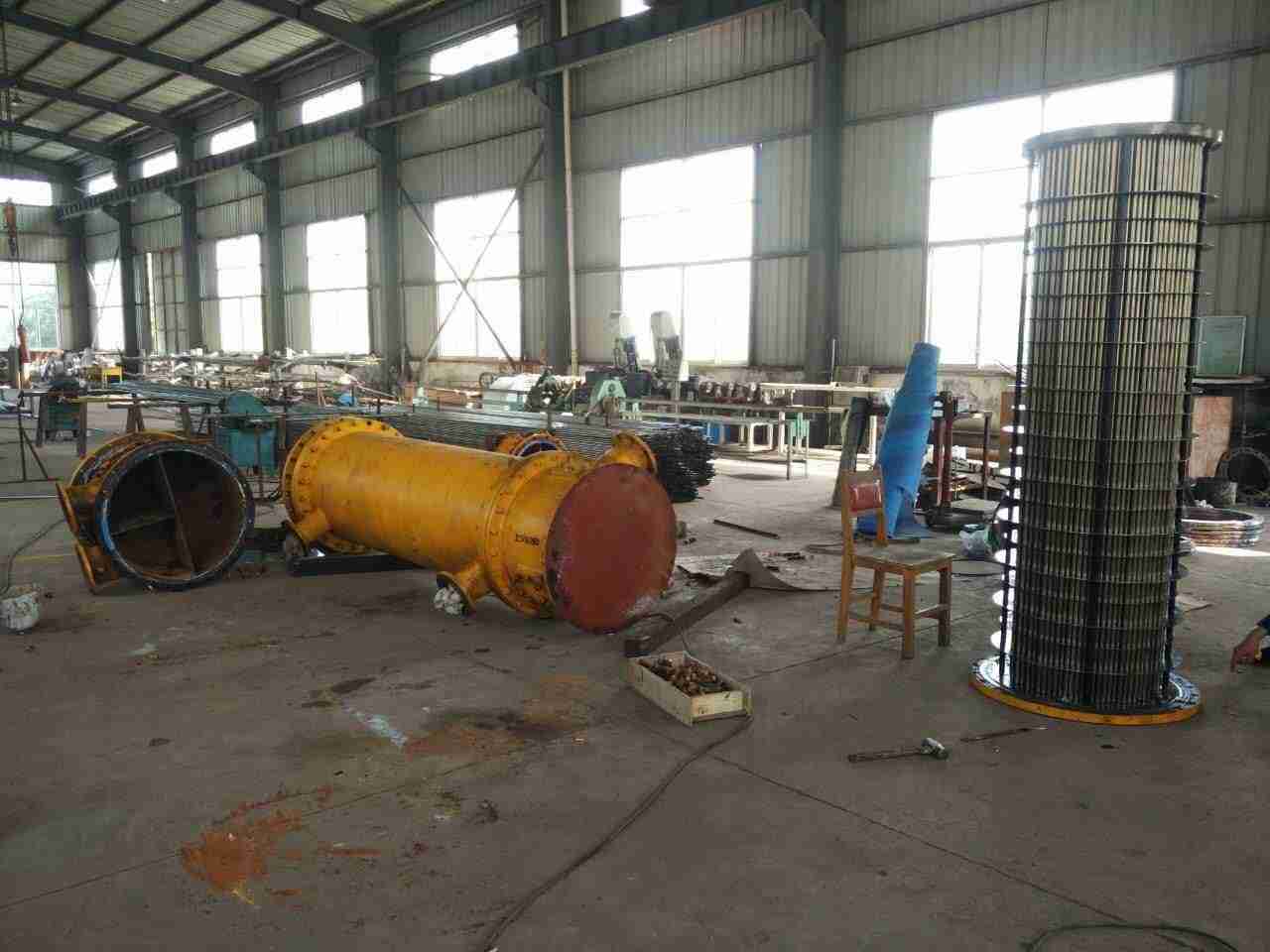
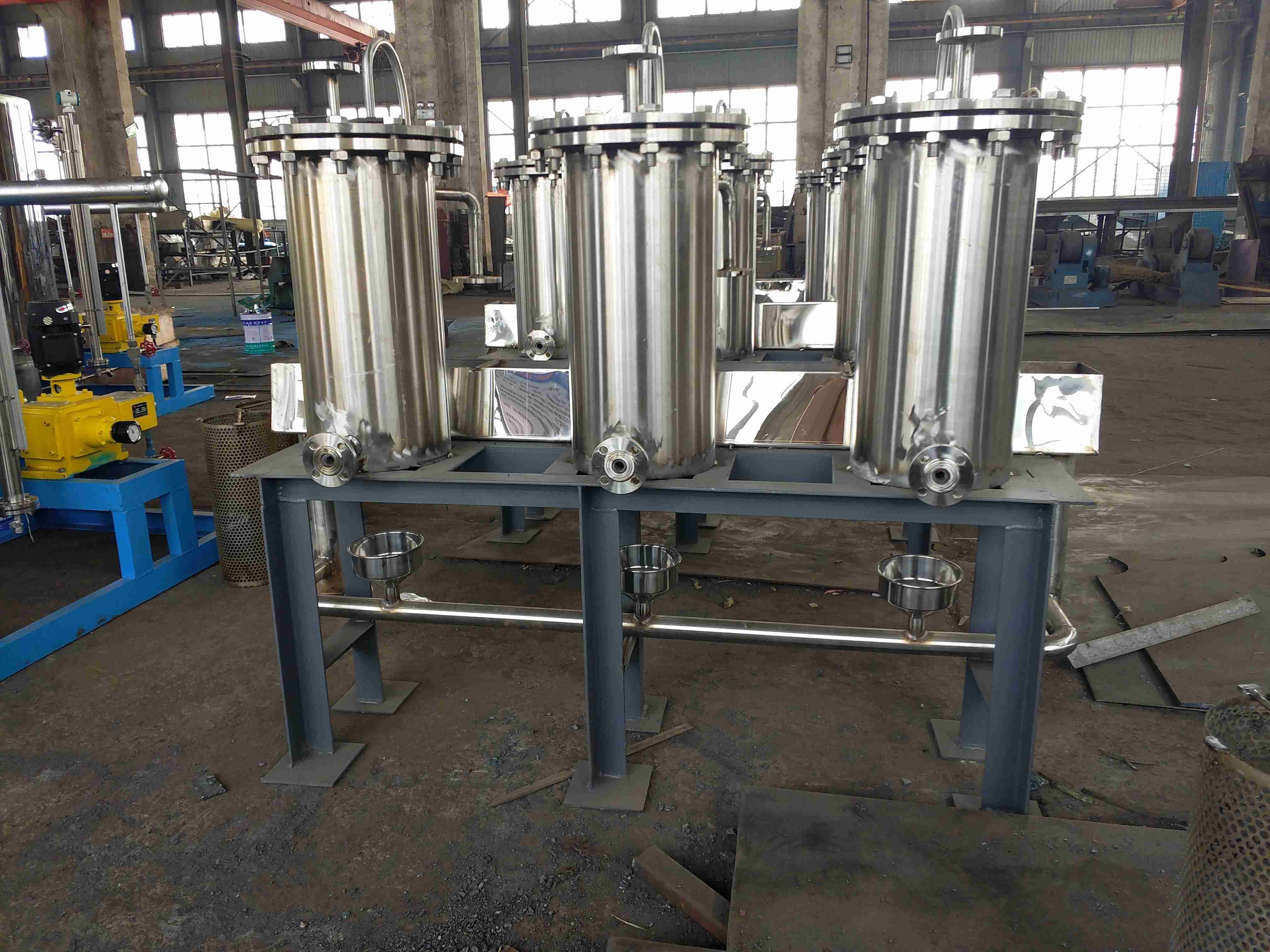
A steam seal cooler is a heat exchanger that recovers condensate from the steam and gas mixture from the shaft seal, and the air is discharged by an air extractor installed on the cooler- Usually, the main condensate is used as the cooling medium. The steam seal heater generally adopts a horizontal U-shaped tube surface heat exchanger (as shown in the figure below), and the pipe material is stainless steel pipe. In addition to expansion joint, the pipe also needs to be sealed and welded with the pipe plate; HSn-70-1 tin brass is also used, which is fixed on the tube plate by expanding the tube bundle to the U-shaped tube end freely. But for critical and critical unit pipes, stainless steel must be selected. The water level inside the shell should be equipped with indicators and monitoring devices. For horizontal heat exchangers, special attention should be paid to not submerging the cooling pipes with condensed water on the steam side, otherwise it will cause rapid heat transfer. During operation, the main condensate flows into the cooling pipe from the inlet chamber and then turns to the outlet chamber through a U-shaped pipe. After entering the shell, the steam and gas mixture circulates outside the pipe and transfers heat to the main condensate through the pipe wall. The steam of the mixture condenses into drainage and is discharged through the water seal from the lower drainage port of the shell. Some of the remaining air and non condensable gas mixture are discharged through the air extractor.
铂莱娱乐场Selection and arrangement of pipeline diameter for steam sealing system:
Supply/return steam pipeline diameter:
Equation -:
D1- Inner diameter of steam pipe (mm)
铂莱娱乐场Gs - Steam flow rate inside the pipe, which can be taken as 1.5 times the calculated steam flow rate under the design steam seal clearance (kg/h);
Us - specific volume of steam inside the pipe (m3/kg), check the water vapor quality table;
铂莱娱乐场Ws - Steam flow rate inside the pipe,
You can select according to the table below.
Nominal pipe diameter (mm) allowed - high flow velocity (m/s)
铂莱娱乐场DN32~DN50 35
铂莱娱乐场DN65~DN80 45
DN100~DN150 55
>DN150 70
Steam gas compound pipeline diameter:
Under the conditions of known compound pressure, compound vapor volume, air volume, and air temperature, calculate the vapor partial pressure, air partial pressure, compound enthalpy, and compound temperature, then obtain the specific volume of the compound, and then calculate the pipe diameter using the following formula:
铂莱娱乐场Equation -:
D2- Inner diameter of composite pipe (mm);
铂莱娱乐场Ga - The air volume of the compound inside the pipe, which can be taken as 1.5 times the calculated air volume under the design steam seal clearance (kg/h);
铂莱娱乐场Gs - the steam volume of the compound inside the pipe, which can be taken as 1.5 times the calculated steam volume under the design steam seal clearance (kg/h);
U m - specific volume of compound inside the pipe (m3/kg);
铂莱娱乐场Wm - flow rate of compound inside the pipe,
You can select from the following table,
Nominal pipe diameter (mm) allowed - high flow velocity (m/s)
铂莱娱乐场DN32~DN80 20
铂莱娱乐场DN80~DN150 28
>DN150 36
The pipe and wall thickness of the steam seal heater should be selected based on the pressure and temperature of the medium. When the temperature exceeds 400 ℃, alloy steel pipes should be selected- At 400 ℃, carbon steel pipes can be selected.
Steam seal heater pipeline layout:
铂莱娱乐场The steam supply pipeline should be inclined towards the direction of the incoming steam, with a tilt rate of 1/50, so that when the valve on the steam supply pipeline is closed, the condensate inside the pipeline can be drained towards the incoming steam pipeline.
Otherwise, continuous drain pipes with throttling orifice plates should be installed at each valve.
The sealing and valve stem steam, as well as the steam gas compound pipeline, should be inclined towards the direction of medium flow, with a tilt rate of 1/50.
铂莱娱乐场The pipeline should avoid the 银行卡V银行卡 phenomenon and drainage should be installed at the low position of the pipeline.
When using water spray for temperature reduction, a continuous drainage device should be installed on the outlet steam pipe of the temperature reducer, which can discharge all the water sprayed into the steam seal pipe when the water spray valve is fully open.
The steam seal from the main steam and reheat steam cooling auxiliary steam should be connected from the steam pipe, either vertically or horizontally.
Working principle of steam seal heater:
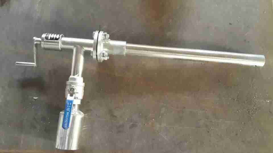
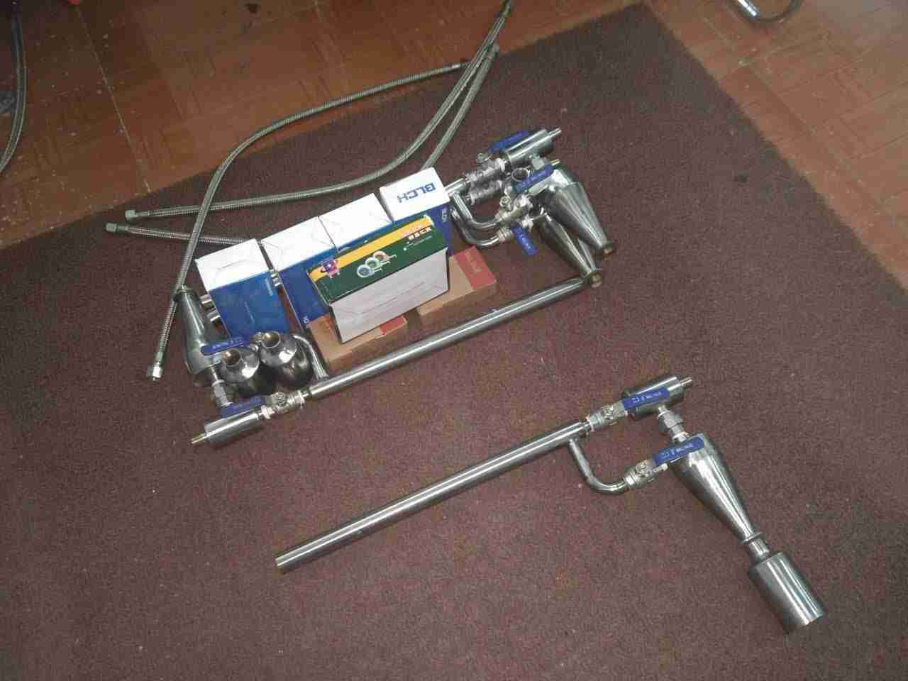
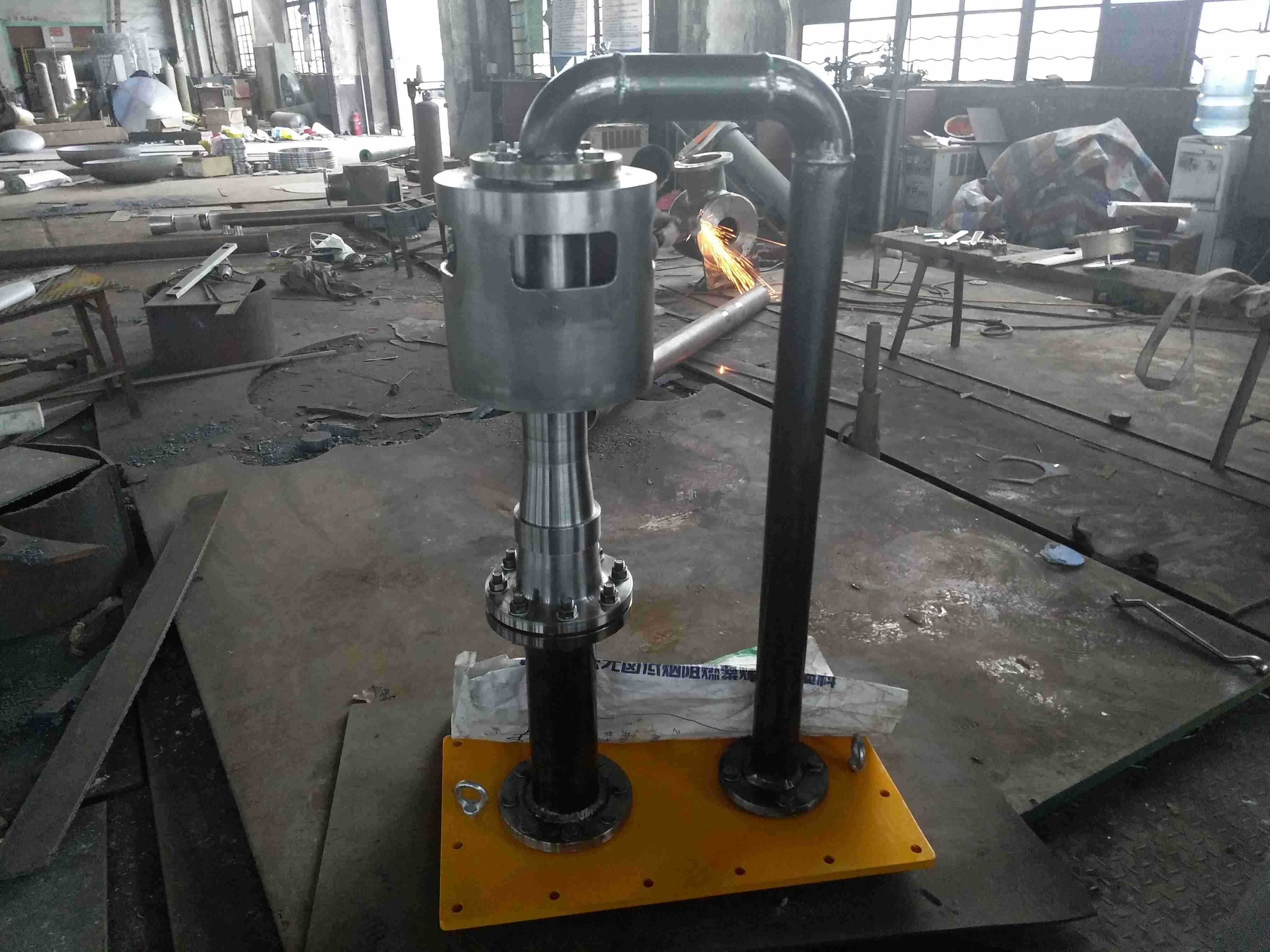
The function of the steam seal cooler is to recover the steam from the - and rear shaft seals, condense it into water, and use it for the boiler. Its working principle and structure are relatively simple. The water from the cooling water enters the water chamber and is divided into two paths, which respectively enter the copper tube bundle of the -- and -- condenser chambers, and is then drawn out from the cooling water outlet. When the steam from the rear steam seal of the turbine enters the condenser from the steam seal, most of the steam releases a large amount of condensation heat when passing through the outer wall of the copper pipe and is condensed into water. The condensate is discharged from the condensate outlet and enters the drainage pipeline. Some air that cannot condense into water and a small amount of residual steam are extracted into the second condenser through an exhaust device composed of a nozzle, a mixing chamber, and a diffuser. In the second condenser, this part of the steam contacts the outer wall of the copper tube bundle for secondary heat exchange. Some of the steam condenses into water, which is discharged from the condensate outlet and also enters the drainage pipeline. Due to the fact that the pressure of the air extraction device when entering the condenser is greater than atmospheric pressure, there is still a mixture of non condensable air and a small amount of residual steam, which is discharged into the atmosphere through the exhaust port.
铂莱娱乐场The parameters required for replacing the steam seal heater pipes are:
铂莱娱乐场1. Original equipment drawings.
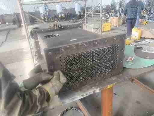
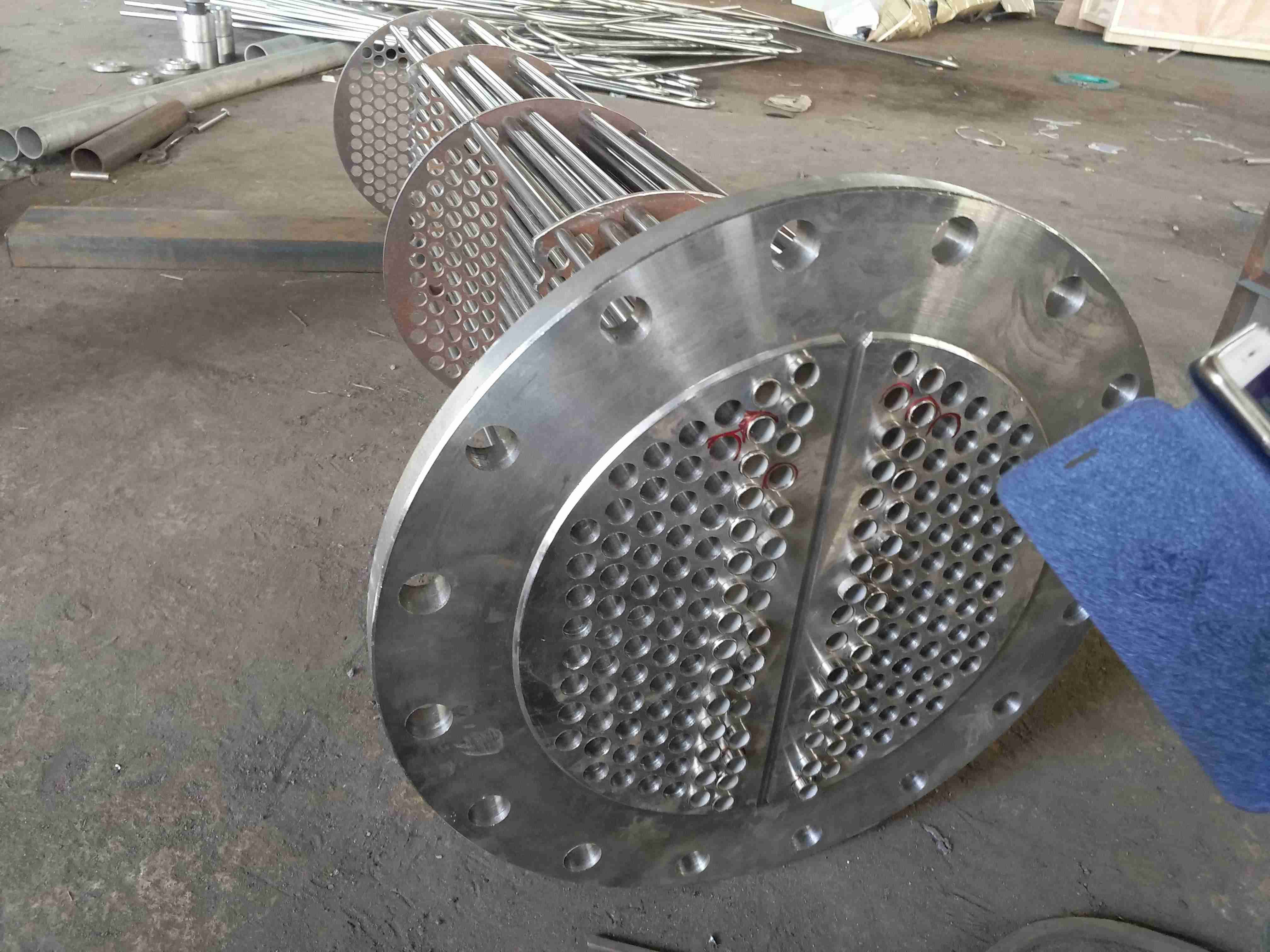
铂莱娱乐场2. Is it to replace the core (partition, tube plate, tube bundle) or just replace the tubes.
铂莱娱乐场3. Pipe type: U-shaped pipe or straight pipe?
3. Material: Stainless steel pipe, copper pipe, 20G pipe (boiler pipe), carbon steel pipe, etc
铂莱娱乐场4. Specific dimensions: diameter? Wall thickness? Manager?
5. If there is a specific piping diagram, please provide it!
6. Inform the location that the original equipment that needs to be replaced must be shipped to our company for replacement. Convenient for water pressure testing, etc. To prevent on-site installation from not being able to enter or experiencing any issues.
铂莱娱乐场The following specifications and technical parameters for 304 stainless steel tubes/316L stainless steel tubes, heat exchange tubes, and cooling tubes are for reference only. For detailed parameters, please contact us by phone! Based on the international pipe bundle, corresponding pipe bundles can be designed according to customer requirements!
| 材料 | O | SI | MN | P | S | NI | CR | MO | n-2000 | n-4200 |
| 304≤ | ≤0.080 | 0.75 | 2.00 | 0.040 | 0.030 | 8.00-11.00 | 18.00-20.00 | - | 2000 | 4200 |
| 304L≤ | 0.035 | 0.75 | 2.00 | 0.040 | 0.030 | 8.00-13.00 | 18.00-20.00 | - |
|
|
| 316≤ | 0.080 | 0.75 | 2.00 | 0.040 | 0.030 | 10.00-14.00 | 16.00-18.00 | 2.00-3.00 | 8300 | 9600 |
| 316L≤ | 0.035 | 0.75 | 2.00 | 0.040 | 0.030 | 10.00-15.00 | 16.00-18.00 | 2.00-3.00 | 4500 | 7043 |
| N | O | H | FC | O | AI | V | 3174 | 4150 | 4680 |
| 不锈钢管∠ | ∠0.02 | 0.05 | 0.015 | 0.25 | 0.12 | 2.5-3.5 | 2.0-3.0 |
|
|
|
| 型号 |
|
| 1 | Φ14×0.5 | Φ14×0.6 | Φ14×0.7 | Φ14×0.8 |
|
|
|
| 2 | Φ15×0.5 | Φ15×0.6 | Φ15×0.7 | Φ15×0.8 |
|
|
|
| 3 | Φ16×0.5 | Φ16×0.6 | Φ16×0.7 | Φ16×0.8 |
|
|
|
| 4 | Φ18×0.5 | Φ18×0.6 | Φ18×0.7 | Φ18×0.8 |
|
|
|
| 5 | Φ19×0.5 | Φ19×0.6 | Φ19×0.7 | Φ19×0.8 |
|
|
|
| 6 | Φ20×0.5 | Φ20×0.6 | Φ20×0.7 | Φ20×0.8 | Φ20×1.0 |
|
|
| 7 | Φ22×0.5 | Φ22×0.6 | Φ22×0.7 | Φ22×0.8 | Φ22×1.0 | Φ22×1.2 |
|
| 8 | Φ25×0.5 | Φ25×0.6 | Φ25×0.7 | Φ25×0.8 | Φ25×1.0 | Φ25×1.2 | Φ25×1.5 |
| 9 | Φ26×0.5 | Φ26×0.6 | Φ26×0.7 | Φ26×0.8 | Φ28×1.0 | Φ28×1.2 | Φ28×1.5 |
| 10 |
| Φ30×0.6 | Φ30×0.7 | Φ30×0.8 | Φ30×1.0 | Φ30×1.2 | Φ30×1.5 |
| 11 |
|
| Φ32×0.7 | Φ32×0.8 | Φ32×1.0 | Φ32×1.2 | Φ32×1.5 |
汽封冷却器换管换芯U型管规格表:
| 序号 | 管外径(mm) | 壁厚(mm) | -心距范围(mm) |
|
|
|
|
|
|
|
|
|
|
|
|
| 1 | φ12 | 1.0~2.0 | 40~500 |
|
|
|
|
|
|
|
|
| 2 | φ14 | 1.0~2.0 | 40~500 |
|
|
|
|
|
|
|
|
| 3 | φ16 | 0.9~2.5 | 60~718 |
|
|
|
|
|
|
|
|
| 4 | φ19 | 1.0~2.5 | 70~480 |
|
|
|
|
|
|
|
|
| 5 | φ20 | 1.0~2.5 | 80~470 |
|
|
|
|
|
|
|
|
| 6 | φ22 | 1.2~2.5 | 80~526 |
|
|
|
|
|
|
|
|
| 7 | φ25 | 1.5~2.5 | 80~634 |
|
|
|
|
|
|
|
|
| 8 | φ27 | 1.5~2.5 | 100~400 |
|
|
|
|
|
|
|
|
| 9 | φ32 | 2.0~3.0 | 150~320 |
|
|
|
|
|
|
|
|
|
|
|
|
|
|
|
|
|
|
|
|
注意:以上为汽封加热器换管U型管材-用规格仅供参考,按实际要求参数为准,详情请联系我们。
不锈钢管各种型号化学成分对照表:
| 管材型号规格 | 碳 | 锰 | 磷
(P) | 硫
(S) | 硅
( Si ) | 镍
( Ni ) | 铬
(CR ) | 钼
(Mo) |
| C | Mn |
| 304 | ≤0.08 | ≤2.00 | ≤0.035 | ≤0.03 | ≤0.1 | ≤8.00-10.50 | ≤18.00-20.00 |
|
| 304L | ≤0.03 | ≤2.00 | ≤0.035 | ≤0.03 | ≤0.1 | ≤9.00-13.00 | ≤18.00-20.00 |
|
| 316 | ≤0.08 | ≤2.00 | ≤0.035 | ≤0.03 | ≤0.1 | ≤10.00-14.00 | ≤16.00-18.00 | 2.00-3.00 |
| 316L | ≤0.03 | ≤2.00 | ≤0.035 | ≤0.03 | ≤0.1 | ≤10.00-14.00 | ≤16.00-18.00 | 2.00-3.00 |
|
|
|
|
|
|
|
|
|
铜管与不锈钢管换热遥遥能对照表:
| 名称 |
|
| 规格 | 材质 | 总体换热系数(W/m².k) | 不锈钢管与铜管比
总体换热系数提高% |
|
|
|
|
| 铜管 |
|
| 1.0(mm) | HSn70-1A | 3682.413869 | 0 |
|
|
| 不锈钢管 |
|
| 1.0(mm) | 304,304l,316,316L | 3460.327347 | -6 |
|
|
| 不锈钢管 |
|
| 0.7(mm) | 304,304l,316,316L | 3760.628476 | 2.214 |
|
|
| 不锈钢管 |
|
| 0.6(mm) | 304,304l,316,316L | 3872.606729 | 5.214 |
|
|
| 不锈钢管 |
|
| 0.5(mm) | 304,304l,316,316L | 3992.015968 | 8.408 |
|
|
|
|
|
|
|
|
|
|
|
介质水-适应氯离子含量指标对照表:
| 管材 |
|
| H68-A | HSn70-1 | TP304,TP304L | TP316,TP316L | TP317,TP317L |
|
|
|
长期遥遥
氯离子含量
(mg/L) |
|
| ≤50 | ≤100 | ≤150 | ≤300 | ≤500 |
|
短期遥遥
氯离子含量
(mg/L) |
|
| ≤100 | ≤200 | ≤300 | ≤500 | ≤1000 |
|
|
|
|
|
|
|
|
|
|
